S = Standard. All Route87 modules and participants must conform to the requirement/standard stated.
RP = Recommended Practice. These are procedures or specifications which are strongly encouraged.
G1 - Generation 1 (Gen 1) standard
G2 - Generation 2 (Gen 2) standard
U - Applies to both Generation 1 and 2 standards
1.0 Introduction
S1.1U The objective of the Gen 1 & Gen 2 Route87 Standards is to provide a platform for prototype 1:87 scale vehicle modeling in a flexible, modular environment. Route87 modules not only provide roadway to display realistic vehicle models, but also emphasize realistic, plausible scenery and environments in which to display vehicles. Gen 2 modules expand on the original Gen 1 standards by giving modelers more depth to work with, as well as providing standards for adding backdrops, front guards, and railroad tracks.
S1.2U Compatibility: The Route87 Standard is a collection of requirements for building scale 1:87 vehicle display modules that can link together with little effort, even when they have never been assembled together before. The Route87 standard allows builders to create realistic dioramas to display their 1:87 vehicles & allows them to connect to other builders� dioramas effortlessly.
S1.3U A Route87 module is a free-form module that conforms to the Route87 Standard as outlined below.
S1.4U A Route87 module can be any length.
S1.5U A Route87 module can vary in width between ends but must conform to the specified end dimensions shown below.
S1.6U A Route87 module can be one section or a set of two or more sections that form a module.
S1.7U The Route87 Standard governs the mating ends of the module.
S1.8U Currently, the Route87 Standard supports only 2 lane roads.
2.0 Frame and Structure
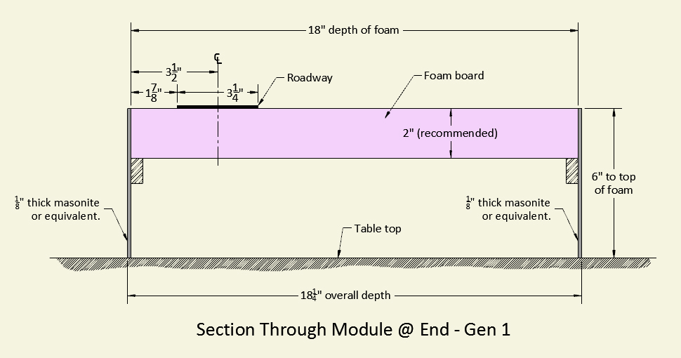
S2.1G1 All Gen 1 Route87 modules shall be of 18-1/4� overall depth as measured from front edge of fascia sideplate to rear edge of rear sideplate.
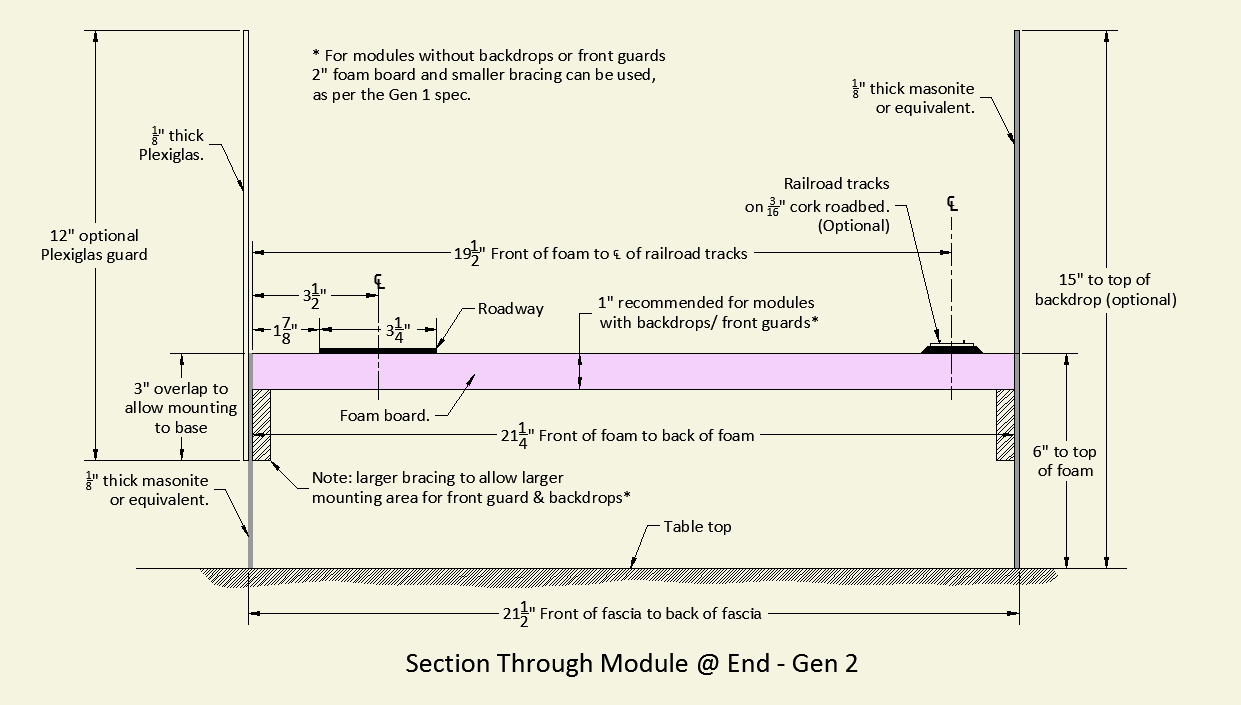
S2.1G2 All Gen 2 Route87 modules shall be of 21-1/2"� overall depth as measured from front edge of fascia sideplate to rear edge of rear sideplate.
S2.2U Sideplates are defined as the front-facing and rear-facing vertical support structure.
S2.3U Sideplates shall be 1/8 inch masonite or equivalent.
S2.4U The distance from the bottom of the sideplate to the top of sideplate will be 6 inches as measured from a smooth, level tabletop.
R2.5U It is recommended endplates at module mating ends be omitted from modules.
R2.5.1U If endplates are used, roadway and scenery must cover the endplates� top and edges.
RP2.6G1 Two inch thick extruded foam insulation may be used for the roadway and scenery base and suspended between the masonite (or equivalent) sideplates.
RP2.6G2 One inch thick extruded foam insulation may be used for the roadway and scenery base and suspended between the masonite (or equivalent) sideplates.
S2.7U The edge of the roadway at the ends shall be 1-7/8 inches from the front edge of the foam base (not the front edge of the sideplate).
S2.7.1U The centerline of the roadway at the ends shall be 3-1/2 inches from the front edge of the foam base(not the front edge of the sideplate).
S2.7.2U The roadway may deviate from the edge of the module at points in the module but must conform to the dimensions stated above at the end of the module.
3.0 Roadway
S3.1U The roadway shall be 3 1/4 inches wide at the end of the module.
S3.2U The top of the road surface shall be 1/16 inch above the top of the foam surface at the end of the module.
RP3.3U Busch roadway material is recomended for the road surface. Product #9710.
4.0 Scenery
S4.1U All foam base shall be hidden by some form of scenery.
S4.2U General module fascia color shall complement scenery and not draw attention from the scene.
S4.3U Scenery at the mating ends shall have a flat profile measuring 6 inches in overall height from tabletop.
S4.4G1 Gen 1 modules will not have a backdrop.
S4.4G2 Gen 2 backdrops are recommended and encouraged.
S4.5U All Gen 1 modules(18-1/4� depth) will be displayed together (contiguously) and all Gen 2 modules (21-1/2" depth) will be displayed together.
5.0G2 Gen 2 Backdrops
S5.1G2 Backdrops shall be constructed of 1/8 inch Masonite (or equivalent).
S5.2G2 Backdrops shall be 15 inch overall height measured from tabletop.
S5.3G2 Backdrops shall be removable for ease of construction and maintenance. Backdrop panels attach to rear sideplate and/or underlying framework.
S5.4G2 Currently there are no requirements or restrictions to backdrops except overall dimensions and coverage.
S5.5G2 Backdrops must be scaled correctly for 1:87 scale viewing.
S5.6G2 Backdrops must cover entire backdrop area, top to bottom including edges of backdrop.
6.0G2 Gen 2 Plexiglas Front Guard (Optional)
RP6.1G2 Plexiglas guard is recommended to protect scenery and vehicles from unwanted viewer contact.
RP6.2G2 If installed, Plexiglas guard shall be constructed of 1/8 inch material, 12 inches tall.
RP6.3G2 If installed, Plexiglas guard shall be mounted to maintain overall height of 15 inches. This allows 3� overlap of Plexiglas guard and front fascia (sideplate) to accommodate fastening.
RP6.4G2 Plexiglas guard must cover mating ends� edges so that no gaps exist in Plexiglas guard from one module to another.
RP6.5G2 A wooden support framework may be used under the one inch foam core board to fasten the removable backdrop and optional Plexiglas to.
7.0G2 Gen 2 Railroad Track (Optional)
RP7.1G2 If desired, railroad track that will continue to the ends of your module that will link to other modelers� modules must be placed in accordance with the above construction drawing. Railroad track will follow a similar consistent placement format as roadway dimensions.
RP7.2G2 Railroad track is for static display purposes only and is not designed or intended to be electrified.
RP7.3G2 Plastic (insulated) rail joiners will be used to connect modules together for aesthetic reasons only.
RP7.4G2 Centerline of railroad track is to be 19-1/2 inches from the front edge of foam at the ends of module.
RP7.5G2 Railroad track shall be on top of 5mm (or equivalent) foam or cork roadbed material at ends of module. See drawing for location specifications.
RP7.6G2 Railroad track and roadbed material shall be ballasted. Ballast color shall be light, medium or dark gray (or a combination of these). Ballast size shall be fine or medium (or a combination of these).
RP7.7G2 A removable railroad track bumper shall be placed at the end of track. Bumpers will be left in place if the module next to yours doesn�t include track.
RP7.8G2 If an adjoining module contains track, bumpers will be removed and the track connected using plastic track connectors.
| Gen 1 Drawing | Gen 2 Drawing | |
|
| |
| (Click to enlarge) | (Click to enlarge) |
Revision History
9/1/2014
S1.4 [Changed; length requirement eliminated] A Route87 module can be any length between 24 inches and 48 inches.
S2.1 [Changed; added definition and dimension for depth]
S2.1 [Changed to S2.2; definition added for �sideplate�]
Subsequent renumbering of all S2.n items
S2.1 [Changed to include height baseline reference from tabletop] The distance from the bottom of the sideplate to the top of the undecorated foam base will be 6 inches.
RP2.5 [Changed for clarity] It is recommended to leave end plate off the modules.
RP2.6 [Changed to eliminate �foam core�] Two inch thick foam core board can be used for the base and suspended between the masonite sides.
S3.2 [Changed 1/8 to 1/16] The top of the road surface shall be 1/8 inch above the top of the foam surface at the end of the module.
S4.1 [Removed "benchwork"] All benchwork/foam base shall be hidden by some form of scenery.
S4.3 [Changed for clarity] Scenery at the endplates shall have a flat profile.
Generation 2 standards added